
Composite Technology & Engineering Capability

Engineering Capability

Complete FRP
Engineering Chain

SUDURA integrates material science, tooling engineering, process control, and validation capability to support reliable composite product development from concept to mass production.

SUSDURA Composite Engineering 08 Stages
  1. 01

    Application
    Requirements

  2. 02

    Material System
    Engineering

  3. 03

    Product & Structural
    Design

  4. 04

    Tooling & Mold
    Engineering

  5. 05

    Molding Process
    Control

  6. 06

    Testing &
    Validation

  7. 07

    Post-Processing
    & Assembly

  8. 08

    Production
    Release

01 / Application-Driven Design

Design Starts from Real Operating Conditions

Every FRP product begins with application requirements. SUSDURA evaluates electrical insulation, mechanical load, flame resistance, weatherability, IP protection, dimensional tolerance, chemical resistance, assembly conditions, and lifecycle expectations before defining the material system and manufacturing route.

Application Requirement Engineering Focus
  • 01Electrical Insulation CTI, dielectric strength, arc resistance
  • 02Fire Safety Flame retardancy, heat resistance, smoke control
  • 03Outdoor Durability UV, moisture, corrosion, weatherability
  • 04Mechanical Strength Load, stiffness, impact resistance
  • 05Dimensional Accuracy Shrinkage, tolerance, warpage control
  • 06Protection Level Sealing, water ingress, IP requirement
  • 07Cost Target Material efficiency, cycle time, tooling strategy
Image placeholder
1:1 recommended
02 / Material System Engineering

Resin, Fiber, Filler & Additive Engineering

SUSDURA engineers complete material systems by optimizing resin matrix, fiberglass reinforcement, fillers, pigments, curing systems, flame-retardant additives, UV stabilizers, release agents, and low-shrinkage systems to meet application-specific performance targets.

M1 / Resin Matrix Systems

Matrix Types

UPRVEEPPUPhenolicThermosetThermoplastic

Key Performance

  • Electrical insulation
  • Heat resistance
  • Chemical resistance
  • Mechanical strength
  • Flame resistance
  • Processing stability
03 / SMC & BMC Formulation Technology

Custom SMC & BMC Compounds for Stable Molding

Our formulation capability focuses on molding stability, fiber distribution, flow behavior, shrinkage control, curing response, surface quality, flame resistance, and electrical insulation performance.

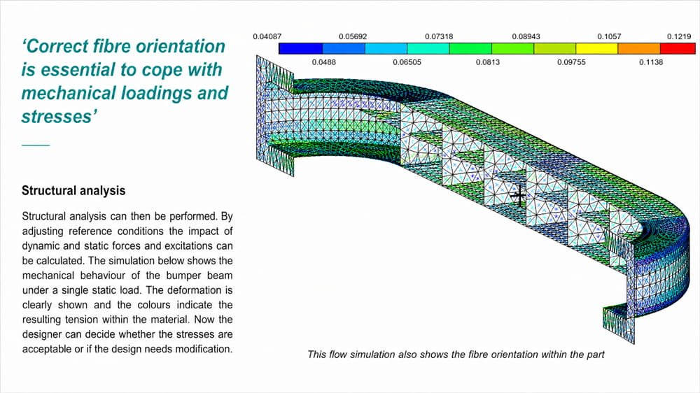
FIG.01 / Mold-Flow Simulation
Mold-flow simulation showing fiber orientation and resin flow front across the part
Flow front & fiber orientation prediction for cavity filling.
FIG.02 / Structural FEA
Structural finite element mesh analysis of a bumper beam under static load showing stress distribution
Stress & deformation under static load on the molded structure.
  • 01

    Flowability

    For complex cavity filling and thin-wall structures.

  • 02

    Shrinkage Control

    For dimensional accuracy and reduced warpage.

  • 03

    Fiber Distribution

    For stable strength, stiffness, and impact resistance.

  • 04

    Curing Behavior

    For cycle efficiency and consistent mechanical properties.

  • 05

    Surface Quality

    For sealing, coating, and appearance requirements.

  • 06

    Flame & Insulation Performance

    For electrical, energy, and transportation applications.

04 / Design for Manufacturing

Designed for Function. Engineered for Production.

A successful SMC/BMC product must balance performance, tooling feasibility, molding behavior, production efficiency, and long-term field reliability. SUSDURA develops product structure, material selection, mold design, and process parameters in parallel to reduce development risk and improve manufacturing consistency.

01 Ribs

Ribs and bosses strengthen and stiffen SMC/BMC parts, but on Class A outer panels they're avoided — they can create sink marks, localized depressions caused by the non-uniform cooling and shrinking of the material. Harmless on non-appearance surfaces, but a serious issue on cosmetically critical parts, depending on geometry and shrinkage rate.

On non-Class A designs, sinks are minimized or eliminated with the right combination of draft angle, radii, and rib thickness.

sink
Sink forms opposite the rib, where the junction cools slower than the wall.

02 Radii

The recommended radii is 2mm minimum for inside corner radii and 1.5mm minimum for outside corner radii — smooth transitions let material flow and cool evenly.

2 mm min. inside radius
1.5 mm min. outside radius
preferred not recommended
Figure 3-7 — preferred design for outside radii vs. design not recommended.
05 / Tooling & Mold Engineering

Mold Engineering Built Around Process Reality.

Mold design directly determines part accuracy, surface quality, cycle stability, insert reliability, and production efficiency. SUSDURA develops tooling based on material flow, curing behavior, temperature balance, venting, insert positioning, ejection, and shrinkage compensation.

FIG.08 General tool arrangement
Mold cross-section, general tool arrangement 1 2 3 4 5 6 7 8 9 10

注:图上10个标注位置是根据图纸特征推测放置的草稿,请核对每个编号是否指向了正确的零件,如有偏差请告诉我具体应指向的位置,我会逐一修正坐标。

06 / Compression Molding Process Control

Controlled SMC/BMC Molding Parameters.

SUSDURA controls compression molding through material charge layout, mold temperature, closing speed, pressure curve, curing time, venting, insert positioning, and demolding strategy to achieve stable dimensions, surface quality, and mechanical performance.

Technical parameters
Process parameter Why it matters
Mold temperature Cure stability and surface finish
Press pressure Fiber flow, compaction, and density
Charge pattern Filling balance and weld line control
Closing speed Air release and fiber orientation
Curing time Mechanical strength and cycle efficiency
Venting Porosity and trapped air prevention
Insert position Pull-out strength and assembly reliability
Demolding Surface protection and deformation control
Factory tour
07 / BMC Injection & Transfer Molding Technology

Precision Molding for Complex Electrical Components.

For small, detailed, and high-volume components, BMC injection and transfer molding provide excellent flowability, dimensional stability, and electrical insulation performance. SUSDURA applies process control to ensure cavity filling, insert bonding, insulation reliability, and batch-to-batch consistency.

Suitable product types
01

Electrical connectors

02

Insulation supports

03

Switchgear parts

04

Circuit breaker components

05

Sensor housings

06

Small precision structural parts

08.1 / Post-Processing & Assembly

From Molded Parts to Production-Ready Components.

Beyond molding, SUSDURA provides machining, cutting, insert assembly, sealing, hardware installation, and final assembly to deliver production-ready composite components.

01

Machining

CNC machining / drilling / cutting / trimming

02

Surface Finishing

Painting / coating / PVD / polishing / sealing

03

Bonding & Assembly

Structural bonding / insert placement / hardware installation

04

Final Inspection

Dimensional check / appearance audit / function test

08.2 / Testing & Validation

Performance Verified Before Production.

SUSDURA validates material systems, samples, and finished products through mechanical, electrical, environmental, flame-resistance, dimensional, and application-focused testing before production release.

Test matrix
Test areaTypical validation
MechanicalTensile, bending, impact, pull-out strength
ElectricalDielectric strength, CTI, insulation resistance
Fire SafetyFlame retardancy, heat resistance, smoke-related performance
EnvironmentalUV, moisture, corrosion, aging
DimensionalCMM, tolerance, warpage
ProtectionSealing, waterproofing, IP-related checks
ProcessSample approval, production trial, process capability
FIG.09 Dimensional capability study — cavity mean analysis
Image placeholder — capability chart
FIG.10 Statistical process control — conformity analysis
Image placeholder — SPC chart
08.3 / Failure Prevention & Problem Solving

Process Knowledge That Prevents Failure.

SUSDURA identifies potential molding and application risks before mass production by analyzing root causes and optimizing material formulation, mold design, process parameters, and quality controls.

Failure prevention matrix
Common risk Possible cause Engineering control
Porosity Trapped air, moisture, poor venting Venting design, moisture control, pressure optimization
Warpage Uneven shrinkage, fiber orientation, temperature imbalance Mold temperature balance, charge pattern, shrinkage control
Delamination Poor curing, weak bonding, contamination Cure control, surface preparation, material optimization
Incomplete Filling Low flow, poor charge layout, insufficient pressure Flowability adjustment, charge design, pressure control
Cracking Stress concentration, over-cure, poor structure Rib design, radius optimization, cure control
Weak Insert Pull-Out Poor insert geometry or bonding Knurling, undercut, surface treatment, insert positioning
Weld Line Poor flow path or design Flow path optimization, weld line relocation, material layout

Join Us

Ready to Explore the Opportunities
SUSDURA Has to Offer?

We look forward to partnering with you to create endless possibilities together.

Click Here »
Scroll to Top